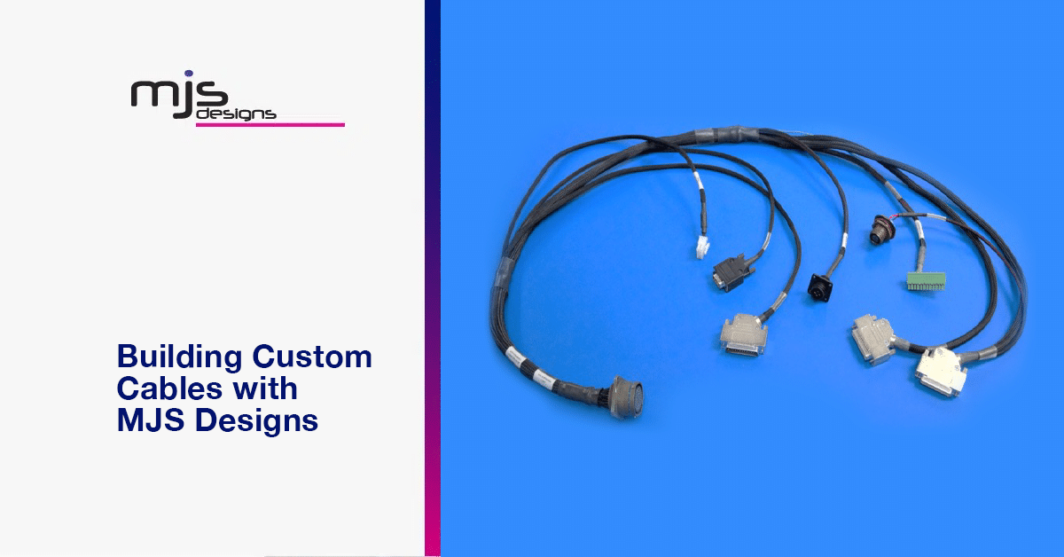
Custom cables are an essential component of many electromechanical systems and box build assemblies. They connect various components such as sensors, switches, and power supplies, and to carry electrical signals from one point to another. Custom cables are often required to meet specific requirements such as size, length, and functionality. At MJS Designs, we understand the importance of having high-quality cables that meet your specific needs. Here is a basic guide detailing custom cable assemblies.
Components Required for Building Custom Cables
The exact components required for building custom cables will depend on the specific needs of your project. However, some of the most utilized components include:
Cable:
The cable is the backbone of any assembly. It carries the electrical signals from one point to another. Cables come in different sizes, types, and materials to meet specific requirements.
The most common types of cables used in custom cable assemblies include:

Ribbon Cables
These cables handle general data transmission. They are flat and wide with multiple conductors aligned in a row.
Coaxial Cables
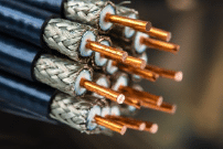
Coaxial cables are best suited for high-frequency applications such as radio and television broadcasting. They consist of an inner conductor surrounded by a conductive shield.
Twisted Pair Cables
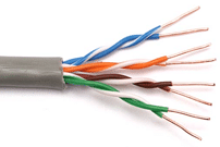
These cables are utilized for networking and data transmission and are made up of two insulated copper wires twisted together.
Multi-Conductor Cables
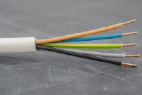
Multi-conductor cables support a wide variety of applications and are made up of multiple conductors grouped together within the same cable sleeve.
Connectors:
Connectors join cables to other components such as switches, sensors, and power supplies. There are different types of connectors, such as crimp connectors, solder connectors, and insulation displacement connectors.
Crimp connectors are the most common type of connector in custom cable assemblies. They are simple and can be installed onto the cable using a crimping tool. Crimp connectors are comprised of two parts: crimp contacts and a crimp housing. These are described in more detail below.
Solder connectors are applied when a stronger connection is required, such as in high-vibration environments. The connection is created by soldering the cable conductors directly to the target connector.
Insulation displacement connectors (IDCs) are applicable for low-cost requirements and can be easily inserted into the cable insulation. IDCs are typically paired with ribbon cable, whereas crimp and solder connectors are usually utilized with single conductor wire found in multi-conductor cables, coaxial cables, and twisted pair cables.
Crimp Contacts:
Crimp contacts are metal pins or sockets that are crimped onto an exposed wire lead. This is accomplished by using a crimping tool to form the metal frame around the conductor to create a firm connection. Crimp contacts can usually be found in 2 finishes: tin (low-cost applications) and gold (high-reliability applications). The crimp contact allows for an electrically solid connection between the cable and the mating connector.
Crimp Housing:
Crimp housings are plastic moldings that surround the crimp contacts and ensure they stay properly aligned. These housings can have latching mechanisms that ensure the connector does not disconnect when subjected to shock and vibration. In order to remove a crimp housing from a mating connector, the housings normally need to be pressed down on the locking latch to release the connector.
Sleeving:
Sleeving protects the cable from abrasion and wear. It also provides an additional layer of insulation and gives the cable a more finished appearance. Sleeving can be made from different materials such as PVC, nylon, and Teflon. PVC sleeving is the most common sleeving material as it is cost-effective and offers a solid protection. Nylon sleeving is more durable and can withstand higher temperatures. Teflon sleeving is more expensive but offers the highest level of protection.
Heat shrink tubing:
Heat shrink tubing protects and insulates the connectors. It is made from thermoplastic material that shrinks when heat is applied. Heat shrink tubing is essential when solder connectors are in use, as it provides insulation between the solder leads, thus preventing unintended shorts between connector pins. It also provides environmental protection and improves the overall appearance of the cable. Heat shrink tubing is available in different sizes and colors to meet the specific requirements of the project.
Cable Ties:
Cable ties (or zip ties) secure multiple cables/wires and prevent tangling in long cables. It is common to apply sleeving or heatshrink over the cable ties to hide them and create a more polished appearance.
Cable Labels:
Cable labels identify the purpose for a cable, where it should be used, and which signals are present in the cable. The labels are printed with custom text and are usually wrapped around a section of the cable. This ensures the label is easily visible and will not snag as the cable brushes walls and other devices. Labels are very important in a lab setting, or for testing purposes. It is also recommended to include labels on very complex cable assemblies that have multiple connectors on each end.
Tools Required for Building Custom Cables
The tools required for building custom cables include:
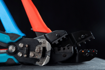
Wire strippers:
Wire strippers remove the insulation from the wire to expose the conductors. This is needed when using crimp or solder connectors. However, when utilizing insulation-displacement connectors, they will displace the insulation themselves so wire strippers are not required. Wire strippers come in a variety of sizes and designs, ranging from handheld manual tools to automatic machines that can strip multiple wires at once. Some wire strippers also have additional features, such as crimpers for attaching connectors to the stripped wire ends. When selecting a wire stripper, it is important to choose one that is appropriate for the wire sizes and types that will be worked with. Selecting the wrong tool can result in damaged wires or poor connections, which can be dangerous or cause problems with electrical equipment.
Crimping tool:
A crimping tool attaches crimp contacts to the cable. Each wire will need to be crimped individually with the manufacturers recommended tooling. By using the manufacturer recommended tooling, the most consistent and reliable results will be achieved. However, this may become expensive when building cables with different crimp connectors as a separate crimping tool will need to be purchased for each connector product line.
Crimp Insertion / Extraction tools:
Crimp insertion and extraction tools insert and extract crimp contacts in crimp housings. These tools prevent the insertion or extraction action from damaging the crimp contacts or the plastic crimp housing.
Soldering iron:
A soldering iron solders the connectors onto the cable when a stronger connection is required. This is only needed when a solder connector is required.
Heat gun:
A heat gun applies heat shrink tubing to the connectors. The heat gun is set to the proper temperature and heats the heat shrink tubing around the cable. This forces the heat shrink tubing to tighten and mold around the cable.
Cable tie gun:
A cable tie gun applies cable ties to the cables so they do not move or tangle. A cable tie gun makes it much easier and quicker to install cable ties in long, complicated cable assemblies.
Label Printer:
A label printer prints custom text onto cable labels. This allows for each cable (or cable section) to be labeled with a unique, fully customizable name that will be easy for operators to understand the functionality of the cable.
Overall Build Process for Custom Cables
The overall build process for custom cables includes the following steps:
Cable preparation:
The cable is cut to the required length and stripped using wire strippers to expose the conductors. The cable is prepared in a straight line, eliminating potential kinks or bulges in the finished cable.
Connector assembly:
The connectors are attached to the cable with a crimping tool or soldering iron, depending on the specific requirements of the project. This is usually the longest step as it requires the technician to manually install each individual conductor of the cable to the connector, one wire at a time. Most custom cables have connectors on both ends, so each wire will be terminated to a connector twice.
Adding insulation:
Heat shrink tubing is added to the connectors to protect them from environmental factors and to provide an additional layer of insulation. The heat shrink tubing is applied using a heat gun.
Applying Sleeving:
Sleeving is added to the cable to protect it from abrasion and wear. The sleeving can be applied using heat or by sliding it over the cable.
Testing:
The cable is tested to ensure that it meets the specific requirements of the project. This includes testing for continuity, resistance, and insulation resistance. A full pin-to-pin netlist may need to be performed to ensure the cable is built correctly and follows the drawings exactly.
The MJS Designs Difference
Custom cables are an essential component of many electromechanical systems and box build assemblies. At MJS Designs, we understand the importance of having high-quality cables that meet your specific needs. With over 47 years of industry experience, our team of experts can build cables for high-reliability complex applications to even the simplest of cables. Whether you already have complete cable drawings ready for production, or you need custom cables designed for your specific system build, our team of engineers and technicians are ready to help. Contact us today to learn more about how we can assist you with your cable requirements.

